Design Standards
The Design Standards category is used to create, review and edit horizontal and vertical geometry design standards information.
Design standards are used to monitor required curvature and other alignment checks on horizontal Civil geometry elements and slopes and K values on vertical geometry elements.
The standards are stored in a design library (DGNLIB) which can be read-only and stored in a central location for use by all users and referenced by the configuration variable MS_DGNLIBLIST. A DGNLIB is an empty file similar to a seed file where you can set up various MicroStation and Civil resources. An organization can utilize numerous DGNLIBs, both horizontal and vertical standards are stored in one DGNLIB is recommended, but separate from other DGNLIB-type data. If utilizing both Metric and English units, you may want one DGNLIB for each.
The standards are set up within the Explorer. Note the hierarchy from the Explorer is mirrored in the Design Standards Tool Bar pick lists. The hierarchy is customizable to conform to your organization's standards.

The pop-up menu contains numerous utility tools, plus Properties, which is where the individual standard is stored. Note there are different settings for Horizontal vs. Vertical Standards.

The Properties panel is the storehouse for each standard.

Vertical standards use the same pop-up menu options. The Properties include each vertical standard.

The Project Explorer is accessed by Home > Primary. It is more efficient to complete the vertical standards first, as they are referenced when building the horizontal standards.
Right-click on the individual entry and select Properties from the pop-up menu to review the settings.
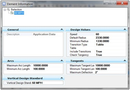
Horizontal Design Standards Properties

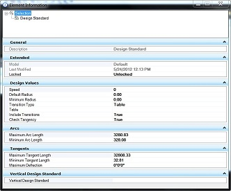
Vertical Design Standards Properties
Create New Horizontal and Vertical Standards
The general procedure is:
-
Determine the hierarchy for vertical and horizontal standards. This also determines how much to create from scratch and how much to copy and paste. Keep in mind users see the hierarchy you build, so keep the names intuitive.
-
Open the DGNLIB file with one of the Civil products. The tools cannot be accessed with only MicroStation loaded. Select File > Project Explorer from the main menu.
-
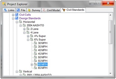
Within Project Explorer, click on the Civil Standards tab.
- Navigate the hierarchy to Horizontal and Vertical. This is the starting point if you are building from scratch.
-
Create the first part of the hierarchy. Avoid the inclination to build the entire hierarchy when you begin. Build the first standard, then copying and pasting into the next standard is easier as many of the field values are the same. Example, the entries for 2 lane versus 4 lane road are the same, and the values are slightly different. Rather than typing everything twice, set up the 2 lane folder, then copy and paste the completed folder to 4 lane and change the values as needed.
-
Select the location where you want to begin, right click and select New from the pop-up menu. A new entry is made in the table entitled Vertical Design Standard. To rename, right click and select Rename and change the name. The hierarchy can be nested.
-
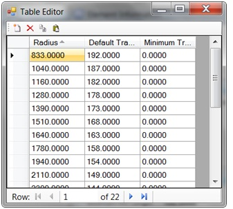
Add the information to the Table Editor (one line for each design speed) and close.
-
Continue adding the rest of the Vertical Standards by copying the first entry and adjusting the Minimum and Maximum Slope, and Difference in Grade, if needed. By copying, you already have the K Value Table information, so it does not have to be re-entered. When using the standards, selection of a horizontal entry of 50 kph or mph will use a default from the vertical list of 50 kph or mph.
-
Transition Table - note the Green Book has Default Transitions, but not Minimum Transitions.
-
Once you have completed a set of entries for one superelevation value (i.e., 4%) it's easiest to copy the entire grouping and paste into your standards. Rename (i.e., from 4% to 6%) then adjust the values within the 6% grouping. This maintains the values within each entry, so you only have to adjust the Transition Table.


The Design Standards branch lists the design standards that are available within the active design model or a DGN library, and initiates the command to create new Design Standards for both Horizontal and Vertical geometry within the active Design model. The Design standards defines Design standards that are used to assist the designer in maintaining required curvature and other checks when performing geometric layouts and are normally based on accepted standards for a geographic area or authority, thus a recommendation is to create and store these in DGN libraries.
To create a new design standard, select Horizontal or Vertical and then right click to select the command New. After clicking on new enter the name of the Design Standard and populate the properties panel as shown.
The properties for each Horizontal standard are:
-
Design Values
- Speed - this is the design speed for the standard.
- Default Radius - this is the radius used to populate commands when initiated.
- Minimum Radius - this is the minimum radius for the corresponding design speed. Utilizing values lower than this radius will cause a warning to be displayed.
- Transition Type - can be by Table or Equation.
- Table - If transition type is table then this is used to populate the table.
- Include Transitions
- Check Tangency
The properties for each Vertical standard are: